
About Your ATA 192 #
Your Cisco ATA 192 telephone adapter box contains the following:
- Your ATA device
- A DCV5 power supply; and
- Your network cable.
Please note that an RJ-11 cable used to connect your ATA to your handset is not included, and may need to be purchased separately depending on the cable used by your phone.
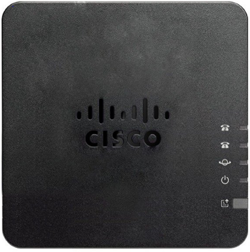
| Icon | Item | Description |
 | Power LED | Steady green: System booted up successfully and is ready for use Slow flashing green: System is booting up Fast flashing green three times, then repeats: System failed to boot up Off: Power is off |
 | Network LED | Flashing green: Data transmission or reception is in progress through the WAN port Off: No link |
 | Phone 1 LED | Steady green: On hook Slow flashing green: Off hook Fast flashing green three ties, then repeats: The analog device failed to register Off: The port is not configured. |
| Phone 2 LED | Phone 2 port is not supported |
| Problem Report Tool (PRT) Button | Press this button to create a problem report using the Problem Report Tool. When pressed, a problem report is generated for the system administrator. Only press this when instructed to do so. | |
 | Problem Report Tool (PRT) LED | Flashing amber: The PRT is preparing the data for the problem report Fast flashing amber: The PRT is sending the problem report log to the server. Solid green for five seconds, then off: The PRT report was sent successfully Flashing red: The PRT report failed. Press the PRT button again to trigger a new report. Blinking red: Press the PRT button once to cancel the blink then press again to trigger a new PRT. |
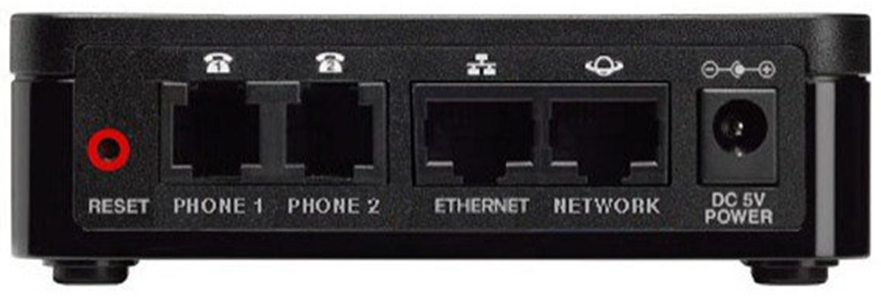
| Item | Description |
| RESET | To restart the ATA, use a paper clip or similar object to press this button briefly. Pressing this for more than 10 seconds restores the device to factory settings and will need to be manually re-provisioned to Horizon. |
| PHONE 1 | Use an RJ-11 phone cable to connect an analog device. |
| PHONE 2 | Not supported. |
| ETHERNET | Use an Ethernet cable to connect your ATA to a device on your network, such as a computer. |
| NETWORK | Use an Ethernet cable to connect to the network. |
| DC 5V POWER | Use the power adapter that was provided to connect to a power source. |
Where to find your MAC address #
Your MAC address can be found on the front of your Cisco ATA 192 box under ‘Serial#’, or on the back of the ATA device itself.
Install Your New ATA 192 #
Before You Begin #
Before you begin the installation, make sure that you have the following equipment:
- Ethernet cable to connect to your network
- Analog device to connect your ATA
- Phone cable to connect your phone
- Uninterruptible power supply (UPS) to provide backup power
Step 1 #
| Instruction | Image |
| Connect the network cable to your network and to the NETWORK port on the ATA. Plug the other end of your network cable into a LAN port on the back of your router |  |
Step 2 #
| Instruction | Image |
| Connect the phone cable to the PHONE 1 port on the ATA and to your analogue device |  |
Step 3 #
| Instruction | Image |
| Connect the ATA power cable to the DC 5V POWER port on the ATA, and plug the power cable into your power source. The power and network icons will show green and may flash whilst being configured. Once the power, internet and port lights are a stable green your ATA device is configured and ready to use. |  |